IO Board Operations & Technical Guide
Type V
>Latest Patch Info
>Updating Firmware
>Installation
>>Vewlix
>>Game Menu Button
>>Powering the board
>>How to link
>>Wrong harness
>Error Codes
Type B
>Latest Patch Info
>Installation
>>blanc
>>connecting audio
>>Powering the board
>>How to link
>Type N
>Latest Patch Info
>Installation
>>Noir
>>Powering the board
>>How to link
Input Lag: 0.3 Frames *JVS' mode only
JVS' Compatible: Yes
・Added Buttons 7 & 8 per player
・Improved button response times
・Fixed rare issue of phantom button presses for the Test button
Type V Board Support
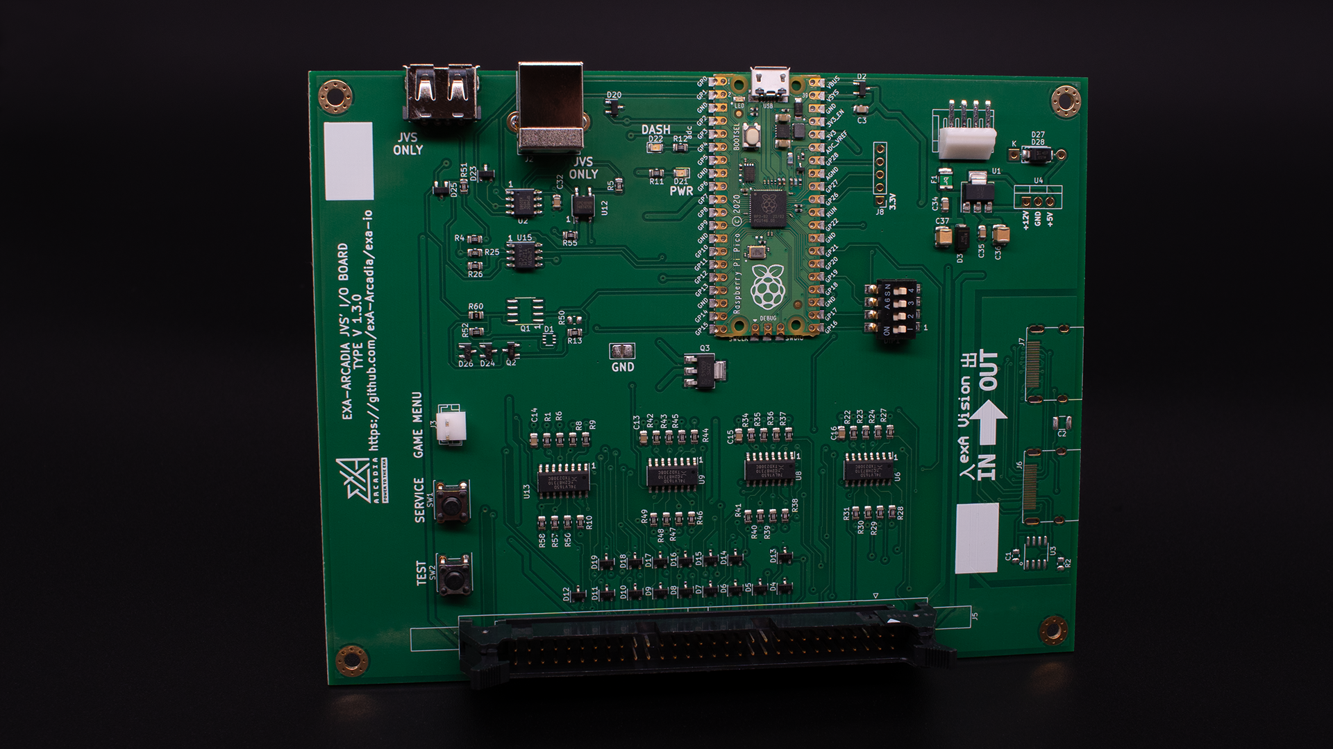
The exA-Arcadia JVS' Type V I/O board is a complete drop in solution for VEWLIX cabinets equipped for JVS or FAST I/O boards.
- Ensure that the cabinet is turned off.
- Disconnect any installed I/O board and remove all wiring & screws.
- Remove the I/O and place the exA-Arcadia JVS' Type V I/O board in its place.
- Proceed to screw in each corner.
- Connect the 60 pin black Hirose connector to (connector #)
- Connect the 4 pin JST NH connector to (connector #)
- Connect the JVS USB Type A connector to (connector #)
show the photo of an installed IO board
VEWLIX cabinets equipped for the USB I/O board do not have the same wiring as VEWLIX setup for JVS or FAST I/O boards.
Visit the exA-Arcadia Shop to select the correct wiring harness for your cabinet.
A Type A to Type B USB cable that is fully wired (one not for charging) is required.
- Connect the Type B side to the Player 1/2 I/O board.
- Run the USB cable through the back of the cabinet into the back side of the other cabinet.
- Connect the Type A side to the Player 3/4 I/O board.
show the photo of an installed IO board linked
Connect the 4 pin JST NH connector to (connector #)
Do not use the micro USB connector to power the I/O board.
Please read the System Support Error page for the IO Error resolution.
Type B Board Support
The exA-Arcadia JVS' Type B I/O board is a JVS solution for blanc cabinets.
- Ensure that the cabinet is turned off.
- Remove the back panel behind the monitor.
- Attach the I/O and secure the exA-Arcadia JVS' Type B I/O board.
- Proceed to screw in each corner.
- Connect the 60 pin black Hirose connector to (connector #)
- Connect the 4 pin JST NH connector to (connector #)
- Connect the JVS USB Type A connector to (connector #)
- Connect the RCA audio connectors from the I/O board to the audio board.
show the photo of an installed IO board
A Type A to Type B USB cable that is fully wired (one not for charging) is required.
- Connect the Type B side to the Player 1/2 I/O board.
- Run the USB cable through the back of the cabinet into the back side of the other cabinet.
- Connect the Type A side to the Player 3/4 I/O board.
show the photo of an installed IO board linked
Connect the 4 pin JST NH connector to (connector #)
Do not use the micro USB connector to power the I/O board.
Please read the System Support Error page for the IO Error resolution.
Type N Board Support
Coming soon.
Please read the System Support Error page for the IO Error resolution.
Still having issues?
Get in touch with our customer support team for more help. Provide the serial # for each product in your request for the quickest service.
Contact Support